
Paper Overview
COmPOSER: Circuit Optimization of mm-wave/RF circuits with Performance-Oriented Synthesis for Efficient Realizations presents COmPOSER as a specification-to-layout automation framework for CMOS RF and mm-wave blocks.
RF/mm-wave automation cannot stop at schematic sizing. At tens of GHz, performance is strongly shaped by passive geometry, routing parasitics, pad access, substrate loss, and the power delivery network. COmPOSER therefore joins circuit synthesis and physical synthesis into one flow that produces layout-ready implementations for LNAs and PAs rather than only optimized component values.
Publication Facts
Publication
arXiv:2603.20486v3, last revised April 21, 2026, accepted for DAC 2026.
Target Circuits
Inductively degenerated cascode LNAs and Class-A power amplifiers operating up to 60 GHz.
Validation Stack
Commercial 65 nm technology, with post-layout validation using EM, extraction, and SPICE tools.
Evaluation Result
Comparable post-layout quality to expert manual design with roughly 100-300x productivity gain.
Why Layout Awareness Matters
Manual LNA and PA design repeatedly alternates between schematic sizing, layout construction, EM extraction, SPICE simulation, and tuning. That loop is slow because the layout is not a cosmetic final step. Spiral inductors, CPWs, shielded transmission lines, bias devices, routing corridors, pads, and decaps affect gain, input and output matching, noise figure, output power, stability, and bandwidth.
COmPOSER addresses that by embedding layout effects into synthesis. Active devices are sized using physics-based equations and technology-dependent operating-point choices. Passive devices, where EM behavior dominates, are selected through learned EM models and inverse design so the chosen dimensions already correspond to realizable layouts.
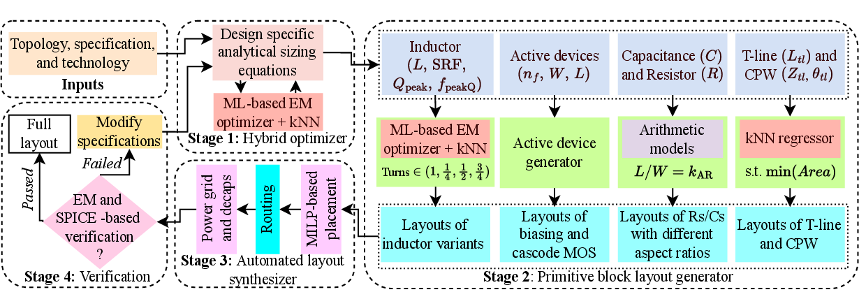
Method in Detail
| Stage | What COmPOSER Does | Why It Matters |
|---|---|---|
| Stage 1: Hybrid optimizer | Combines analytical LNA/PA equations with ML-based EM inverse design for inductors, T-lines, and CPWs. The inductor model uses a random-forest forward model and k-NN inverse search over geometry candidates. | It avoids layout-oblivious sizing while keeping the search fast enough for repeated design exploration. |
| Stage 2: Primitive block generator | Turns optimized dimensions into DRC-clean layouts for cascode and bias MOS devices, resistors, capacitors, spiral inductors, CPWs, and T-lines. It also produces geometry variants such as alternative aspect ratios and terminal locations. | Placement and routing get real physical blocks, not abstract values, and can trade off area, pin access, and routing length. |
| Stage 3: Automated layout synthesizer | Uses MILP-based placement to choose primitive variants, rotations, compact positions, and pad sides. Routing uses a Hanan-grid A* search with net priority, layer preference, width control, and blockage handling, followed by PDN and decap insertion. | The output is a complete implementation-ready layout with pads, internal routing, and power delivery included. |
| Stage 4: Verification and refinement | Runs post-layout EM and circuit-level verification, then tightens constraints and resynthesizes if specifications miss. | The flow closes the loop between schematic intent and physical behavior instead of relying on manual post-layout tuning. |
Passive Modeling Details
- Inductors are represented by geometry parameters such as turns, width, spacing, and inner radius, with predicted inductance, peak Q, peak-Q frequency, and self-resonant frequency.
- The inductor dataset contains 80k generated layouts simulated in Cadence EMX; surrogate accuracy is above R2 = 0.999 for the key EM outputs.
- The inverse design step searches for geometries that satisfy inductance while improving quality factor, peak-Q frequency, and self-resonant frequency.
- For CPWs and T-lines, COmPOSER uses k-NN regression around the requested specification to infer physical dimensions.
- Small inductances below the technology-specific threshold are implemented as T-lines, while larger values are implemented as spiral inductors.
Evaluation Summary
COmPOSER is evaluated on four LNA designs and three PA designs in a commercial 65 nm technology. The LNA set includes multiple single-stage designs and a two-stage LNA. The PA set includes a single-stage 20 GHz PA and two two-stage PAs at 40 GHz and 60 GHz. The evaluation covers post-layout EM- and SPICE-validated performance, stability, area, matching behavior, and runtime.
The Smith chart analysis shows the synthesized matching networks moving from pad impedance through intermediate matching points to final impedances that satisfy the intended input or output matching criteria. The synthesized designs remain stable after PDN parasitics are included.
Ablation and Runtime
- Without EM-aware passive modeling, the ablation shows severe center-frequency shifts: a 60 GHz PA degrades toward 45 GHz and a 60 GHz LNA toward 40 GHz.
- The layout-oblivious ablation also causes substantial performance loss, including PA gain and output-power degradation and LNA gain and noise-figure degradation.
- Stages 1-3 run in minutes: average design-generation time is around 2.58 minutes for LNA cases and 3.10 minutes for PA cases.
- Final EM and SPICE verification dominates runtime: total runtime is about 23.58 minutes for LNA cases and 40.10 minutes for PA cases.
- Against a roughly 70-hour manual LNA baseline, the productivity improvement is about 100-300x.
Flow Stages and Repo Mapping
| COmPOSER Stage | Public Repo Entry Points | Notes |
|---|---|---|
| Stage 1: Hybrid optimizer | perform_initial_sizing.py, lna_stage_1_sizer.py, pa_stage_1_sizer.py, map_initial_size_to_netlist.py | Maps user specs and topology assumptions into sized netlists and stage-1 JSON outputs. |
| Stage 2: Primitive generation | parse_netlist.py, PRIMITIVE_GENERATORS/, PRIMITIVE_OPTIMIZERS/ | Builds primitive GDS blocks and JSON consumed by placement and routing. |
| Stage 3: Layout synthesis | perform_placement.py, generate_routing_inputs.py, perform_routing.py, perform_power_grid_multi_level.py, perform_routing_with_pdn.py, perform_power_grid_with_pdn_routing.py | Generates placement, LEF/DEF-style routing inputs, routed GDS, and PDN-enhanced final GDS. |
| Stage 4: Verification | Not fully bundled as an open-source replacement for commercial EM/SPICE verification | The published validation uses commercial technology and verification tools; the repo exposes the synthesis infrastructure and mock/reference assets. |
Public Repo vs Paper Scope
The public repository is intended to let readers inspect and run the synthesis side of COmPOSER. It includes the open flow, example LNA and PA directories, mock/reference datasets, mock PDK content, primitive generators, placement, routing, and PDN construction. It does not ship the commercial 65 nm PDK, Cadence EMX setup, Calibre extraction flow, or Spectre verification environment used for the published silicon-process validation.
Trying COmPOSER After Reading the Manuscript
- Start with Installation to set up Python dependencies, Gurobi, the router build, and the mock PDK assets.
- Use Quickstart to run one of the included LNA or PA examples and inspect the generated
stage_1,stage_2, andstage_3directories. - Read Configuration before changing specs, topology-specific sizing constants, net weights, placement constraints, routing constraints, or PDN settings.
- Use Examples to understand the difference between user input files, generated netlists, primitive GDS outputs, placement results, routed GDS, and final PDN-enhanced GDS.
The examples are the fastest way to connect COmPOSER's four-stage flow to concrete files. Treat the bundled datasets and mock PDK as reference scaffolding; technology-specific reproduction requires technology-specific datasets, models, rules, and verification tools.
Paper Link
arXiv entry: https://arxiv.org/abs/2603.20486